All sensor data in DataWise® is stored by a numeric identifier which can range from 1 to 2,147,483,647.
The scheme in DataWise® is to associate a physical sensor with a numeric identifier.
To define a new sensor or edit an existing one, select "Define Sensors" from the Configure drop-down menu. The dialog shown below will be displayed:
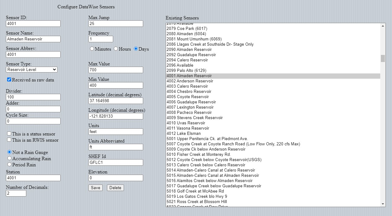
The "Define Sensors" dialog screen. The fields are defined below:
| Field Name | Contents |
|---|---|
| Sensor ID | DataWise number |
| Sensor Name | Arbitrary name for the sensor |
| Sensor Abbrev | Arbitrary sensor abbreviation |
| Sensor Type | The type of physical parameter being measured (see Appendix D for a list of types) |
| Received as raw data | If checked, data is received in raw (non-engineering units) form. Otherwise data is received in engineering units |
| Divider | Used to convert data received in raw format to engineering units. Not used for data received in engineering units. |
| Adder | Used to convert data received in raw format to engineering units. Not used for data received in engineering units. |
| Cycle Size | Currently, used only if data is received in raw form. Maximum raw data value. |
| This is a status sensor | Checked if the bits in a sensor's reading represent the status of some device (e.g., lights on, etc). |
| This is an RWIS sensor | Checked when the numeric values of a sensor reading should be converted to a text value (e.g., ice, dry, wet) upon display. |
| Not a rain gage | Checked when not a rain gage. |
| Accumulating Rain | Checked when the sensor reports accumulated rainfall amounts (e.g., tipping bucket rain gage). |
| Period Rain | Checked when the sensor reports incremental rainfall amounts (e.g, 15-minute rainfall). |
| Station | The station number that this sensor is attached to (if unknown, enter 0 initially). |
| Number of Decimals | For displaying data, the number of digits to the right of the decimal point to display (0-10). |
| Max Jump | The maximum allowed change (in engineering units) between consecutive data values before the data is flagged as invalid. |
| Frequency | The expected reporting interval of the sensor. |
| Max Value | The maximum reading possible for the sensor. Readings above this value are considered invalid. |
| Min Value | The minimum reading possible for the sensor. Readings below this value are considered invalid. |
| Latitude | The north / south location of the sensor in decimal degrees. Used for GIS purposes. |
| Longitude | The east / west location of the sensor in decimal degrees. Used for GIS purposes. |
| Units | The engineering units that the sensor is reporting values in. |
| Units Abbreviated | The abbreviated engineering units that the sensor is reporting values in. |
| SHEF Id | The Standard Hydrometeorological Exchange Format (set to None if not used or unknown). |
| Elevation | Sensor elevation. |