Defining Bits for a Status Sensor
Status sensors are used to monitor the state of remote equipment and/or to control remote equipment.
Each bit in the data value from a status sensor can reflect the current state of some equipment.
If the bit is set to 1, it indicates the equipment monitored by that bit is activated.
If the bit is clear or set to 0, it indicates the equipment is idle or off.
To begin, select
"Status Bits" from the Configure Drop-down menu. The screen below will be displayed.
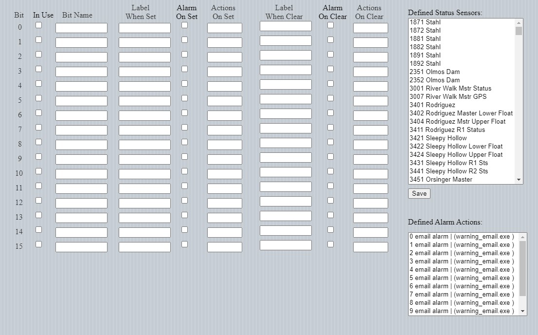
The columns are defined below:
Define Sensors Field Definition
| Column Name |
Contents |
| In Use |
Checked if bit is used |
| Bit Name |
Arbitrary name for the bit |
| Label when set |
What to display when bit set |
| Alarm on set |
Checked when an alarm should be generated when bit goes high |
| Actions on set |
The alarm actions to perform when bit goes high |
| Label when clear |
What to display when bit clear. |
| Alarm on clear |
Checked when an alarm should be generated when bit goes clear. |
| Actions on clear |
The alarm actions to perform when bit goes clear. |
To define the bits in a status sensor
Select a status sensor from the list of Defined Status Sensors on the right.
Existing status bit definitions will be displayed
Click the "In Use" box for all bits to be monitored.
Give each "In Use" bit a name (Bit Name), for example "Gate Status"
Provide labels (Label When Set)for when the "In Use" bit is set and when it is clear or unset
If an alarm is to be generated when a bit goes from 0 to 1, check the "Alarm On Set" box and enter the alarm actions to perform. (Refer to the Alarm Actions section)
If an alarm is to be generated when a bit goes from 1 to 0, check the "Alarm On Clear" box and enter the alarm actions to perform. (Refer to the Alarm Actions section)
Be sure to click the "Save" button when complete.
This figure above shows simple configuration. There are four bits being monitored on status sensor 1871. Bit 0 is flagged as monitoring warning lights on a barrier gate.
When the bit is set, the text displayed is "On" and when the bit is clear, the text displayed is "Off".
The software is set to alarm whenever the bit changes state, either from 0 to 1 or from 1 to 0.
In both cases, alarm action 3 is activated.
Users should familiarize themselves with the section dealing with
available alarms.
When an alarm is generated for a change in bit status, the alarm display will include the bit number, the bit name and the label associated with the bit state, in the example, either "Lights On" or "Lights Off".